Design and construction of lock steel pipe pile cofferdam for super large cap
1.0 Project overview
Chizhou Yangtze River Highway Bridge is located in the section of Guichi River between Anqing and Wuhu in the lower reaches of the Yangtze River. The main navigable span of this bridge has a total length of 1,448 m, and the span of the bridge is arranged as (3 × 48 + 96 + 828 + 280 + 100)m. Also, it is an asymmetric hybrid girder cable-stayed bridge. The north main pier (Z4 pier) foundation cap is round-ended, and its plane outline dimension is 59.5m × 26.8m. The radius of this round end cushion cap is 15.72m, and there are 36 φ2.5 m bored piles set under this cap. The cushion cap is 6.5m thick, with bottom elevation + 4.5m and top elevation + 11.0m. A 2 m high frustum of a pyramid tower base is set on the top of the cap. Its bottom contour size of 44.5m × 19.0m and the top contour size of 40.5m × 15.0m.
2.0 Selection of cofferdam form
For the pile foundation construction of Z4 main pier, it fills the high level of the floor by the soil. Also, it takes a construction method to harden the area outside the piles, forming a construction cushion cap. After this process, the top elevation of the cushion cap becomes + 14.0 m, and the bottom elevation is + 4.5 m. For this project, there is a bottom sealing concrete layer with the thickness of 0.5m designed, as well as gravel cushion layer with the thickness of 0.2m. So, the cutting depth of this cap is over 10m. Moreover, the distance between the shore side of the cap and the dam foot of Yangtze River is only 14m, and the side of Guichi River is only 30m away from Yangtze River. One corner cofferdam is exposed beyond the cap, leading unbalanced soil pressure between the bank and the river. It is necessary to set the position and number of layers of the inner steel walings, so there is a need to consider a cofferdam system with good water-stopping effect, large stiffness, and good stability.
2.1 Double-wall steel cofferdam
The whole rigidity and stability of double-wall steel cofferdam are good, and it is easy to seal water. It also has some limitations; for example, it requires large lifting equipment, which is more suitable for water area construction. As the platform is for land construction, there is a problem for the operation of large lifting equipment, which is difficult to be dismantled and reused.
2.2 Steel sheet pile cofferdam
At the beginning of the construction, steel sheet pile cofferdam is also one of the options. According to the market research, the longest steel sheet pile on the market is 18m, which is Lassen SP-IVw steel sheet piles. For this case, the length of steel sheet piles is required to be at least 26m, which also needs inner steel walings. Lengthened steel sheet pile s a solution, but it is adverse to seal water, and the safety of the foundation pit cannot be guaranteed.
2.3 Locking steel pipe pile cofferdam
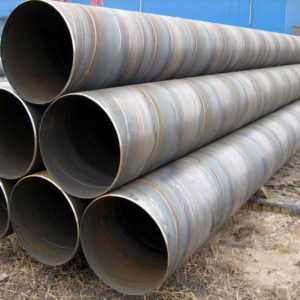
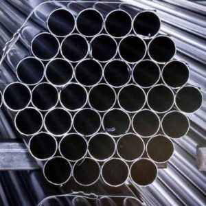
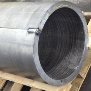
Its high stiffness characterizes the locking steel pipe pile. It also can be manufactured on-site and reused for many times. In this project, due to its own stiffness and internal support system, the overall stiffness and horizontal thrust strength of the cofferdam were significantly enhanced. It has guaranteed the safety of the foundation pit. Moreover, the simple structure system is beneficial to earthwork excavation, reducing the exposure time of the foundation pit. It will effectively shorten the construction period of the cap, and save the cost of the construction. Therefore, the “CO” locking steel cofferdam is selected for this project.
3.0 Design of “CO” locking steel cofferdam
3.1 Dimensions of Cofferdam and the selection of structure
After comprehensive consideration on the geometric dimensions of the cap and the requirement of operation space, the proposed size of foundation pit bottom is 63.2m × 30.3m (1.5m net operating width). Based on the water level, stratum, and topography of the main pier, and the application of the similar locking steel pipe piles in China, Z4 main pier applies φ820×10 (main steel pipe) and 152×8 (female lock port), which has an excellent stiffness. The cofferdam inner support system consists of two layers.
The first layer has an inner support elevation of +11.6 m, and 2HN700 × 300 section steel is used for inner steel walings. 2HN700 × 300 steel and D720 × 10 mm steel pipe are used for inner support. The second layer has an inner support elevation of +8.6 m, and 2HN900 ×300 sections steel is used for steel walings. 3HN700 ×300 sections steel and D820 × 10 mm steel pipes are adopted for inner support.
3.2 Analysis and calculation of cofferdam structure
Boundary conditions for calculation of locking steel pipe pile cofferdam:
The elastic connection is adopted between steel pipe piles to simulate the locking effect of steel pipe piles. External load is loaded along the normal direction of the element. A compression spring is used to simulate between the steel walings and the steel pipe pile. Solidification was used between steel tube bracing and fence to simulate the welding effect. In this project, MIDIS software is used to check the whole and sub-operating conditions, and ANSYS finite element software is used to re-check the whole and sub-operating conditions.
According to the previous process flow, the following load conditions are mainly considered under the most adverse conditions:
Working condition 1:
After installing the top floor support system, the next step is to drive the steel pipe pile to the designed elevation. Under the condition of the construction water level (+ 3.00m), excavation should reach the depth of 1m below the bottom support of the cofferdam (+7.50m), ensuring the dry construction inside the cofferdam.
Working condition 2:
Workers should install the bottom support system and the connection system with the previous support system. Excavation of foundation pit bottom (+ 3.80m) should be processed under the condition of water level of the cap (+ 3.00m), as well as ensuring the dry construction inside the cofferdam.
Working condition 3:
After the concrete of the first and second layers of the bearing platforms are formed, sand is backfilled in the area around the cushion cap, and crown beam concrete is poured at the top. Also, the connection system between the bottom supporting system and the previous supporting system is removed.
According to the calculation results from two analysis software, although there is a slight difference on a certain working condition or component between these two results, the strength and stiffness of each cofferdam component can meet the requirements of the design specification. During the construction process, Construction process, monitoring points of settlement and displacement are set in Z4 main piers, the Yangtze River dam and the track of gantry crane. From the measured data, the maximum displacement of wailing is 26 mm, and gantry crane rail accumulative displacement for gantry crane track is 20 mm.
It was consistent with the results generated by ANSYS, a calculation software, and both of these results are under the construction control. Before the construction, the anti-uplift stability of the foundation pit was checked, and the calculation result for the coefficient of stability is Fs = 3.275 > 1.6 (second safety class), which meets the requirement. Slope stability was calculated by Slide, a slope stability analysis software, the stability coefficient of the most slippery sliding surface next to steel pipe cofferdam is Fs =1.958 > Fst = 1.2. The stability coefficient of the most slippery sliding surface of natural slope is Fs = 1.932 > Fst = 1.3. Both of these two stability coefficients meet the requirements of the specification.
4.0 Conclusion
During the implementation of steel cofferdam of Z4 main pier of north main bridge of Chizhou Yangtze River Highway Bridge, “CO” locking steel pipe pile cofferdam is selected through preliminary investigation and analysis. “CO” locking steel pipe pile cofferdam is the most suitable for this project. During the design process, through discussions and analysis, two kinds of software are used to verify each other and generate calculation results for different working conditions to provide a reliable technical guarantee for cofferdam construction. During the construction process, several construction methods are compared to optimize and adjust each other, which helps to improve construction efficiency and reduce the construction difficulty. A complete set of technical analysis and construction methods guarantee that the locking steel cofferdam is completed within 40 days, which creates favorable conditions for the construction of the platform. Also, this project provides a complete design and construction method for similar projects.


